

How to Build a Complete CUAV Autopilot System

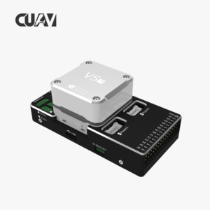
A complete autopilot is an architecture, not a single box. The flight controller depends on clean power, reliable positioning, appropriate data links and sensors that match the aircraft. Planning those parts together reduces adapter problems and makes commissioning easier. The CUAV Drone Components range is organised around these system functions.
Build the architecture in five layers
| Layer | Role | Orkes category or example |
|---|---|---|
| Flight control | Runs estimation, navigation, control and fail-safe logic | Flight Controllers |
| Positioning and heading | Provides GNSS position, velocity and optional RTK or heading | GNSS, GPS & RTK |
| Power | Supplies regulated controller power and measures battery state | CUAV CAN PMU |
| Communication | Carries command, telemetry, correction data or payload information | Telemetry & Data Links |
| Air and environment data | Adds airspeed, compass, range or other mission-specific sensing | Sensors & Airspeed |
Choose the controller and firmware together
Select PX4 or ArduPilot according to the airframe, features and team experience, then verify that the exact controller hardware is supported by the intended firmware release. A configuration from a similarly named board should not be copied without checking the hardware target, sensor orientation and port mapping.
Create a power budget before wiring
List the operating voltage and peak current of the flight controller, GNSS, telemetry, servos, payloads and accessories. Confirm which loads are supplied through the power module and which need separate regulation. Keep propulsion power and sensitive electronics appropriately separated, provide the required backup path and verify that current and voltage measurement are calibrated.
Reserve interfaces and plan failure behaviour
Draw every CAN, UART, I2C, PWM, Ethernet and power connection before assembly. Reserve a service port for setup and logging. Decide what the aircraft should do if GNSS corrections, telemetry, an airspeed sensor or one power source is lost. Those decisions determine whether additional redundancy is useful and which ports must remain available.
Commission one layer at a time
Power and configure the controller first, then add positioning, telemetry and sensors individually. Verify firmware recognition, orientation, calibration and data quality after each change. This makes faults easier to isolate than connecting the complete system at once. CUAV’s official documentation should be used for pinouts, firmware targets and model-specific instructions.
For a project review, send Orkes the airframe type, battery voltage, firmware choice, required positioning accuracy, telemetry distance, payload interfaces and environmental limits. We can then help turn the parts list into a compatible CUAV autopilot system.